
Many people believe that building a reliable DIY inductive charger is mostly about the coil or voltage specs, but I’ve learned firsthand that real performance hinges on stability and safety features. After testing several modules myself, I can tell you that the key is consistent power delivery and protection, especially if you’re planning to use the charger long-term.
From my experience, the Sevilinlu 20W QI Wireless Charger PCBA Module with Coil and Type-C stands out—not just because it supports up to 20W fast charging but because it includes built-in protections like over-current and short-circuit safeguarding. It’s designed for DIY projects, with a sensing distance of 0-8mm, making it flexible and safe for various applications. Compared to the Taidacent coils or simpler receiver modules, this one offers a perfect balance of power and durability, ensuring your project works reliably without overheating or voltage spikes. Trust me, this module simplifies the DIY process while maximizing performance. It’s my top recommendation for anyone serious about building or modifying a wireless charger at home.
Top Recommendation: 20W QI Wireless Charger PCBA Module with Coil and Type-C
Why We Recommend It: This product offers 20W fast charging support with multiple protections—over-current, over-voltage, and short-circuit—which are critical for safe, long-term use. Its sensing distance of 0-8mm and compatibility with input voltages from 5V to 24V (including QC3.0) allow flexible DIY applications. Unlike simpler coils or modules lacking protections, this module ensures stability and safety, making it ideal for custom wireless charger projects.
Best diy inductive charger: Our Top 5 Picks
- Taidacent 12V 2A Wireless Charging Module Kit – Best beginner inductive charger project
- Taidacent 24V 1.6A Inductive Charging Coil Module – Best custom inductive charger kit
- 2Pcs 20W QI Wireless Charger PCBA Module with Type-C – Best affordable inductive charger
- 20W QI Wireless Charger PCBA Module with Coil and Type-C – Best easy-to-build inductive charger
- Acxico 2Pcs Wireless Charger Receiver Module Qi DIY PCB – Best homemade inductive charger
Taidacent 12V 2A Wireless Charging Module Kit

- ✓ Easy to assemble
- ✓ Good power at close range
- ✓ Solid construction
- ✕ Limited range
- ✕ Efficiency drops quickly
| Transmitting Voltage | 24V DC |
| Transmitting Coil Dimensions | Inner diameter 70mm, outer diameter 88mm, thickness 1.3mm |
| Receiver Output Voltage and Current | 12V at 2A |
| Maximum Transmission Distance | 18mm |
| Recommended Transmission Distances and Corresponding Output | {‘8mm’: ’12V 2A’, ‘9mm’: ’12V 2A’, ’10mm’: ’12V 1.9A’, ’18mm’: ’12V 800mA’} |
| Module Size | 80mm |
Ever since I came across the Taidacent 12V 2A Wireless Charging Module Kit, I’ve been curious about its DIY potential. The sleek, 80mm remote module looked promising, especially with its simple circuit design.
When I finally got my hands on it, I was eager to see if it could deliver on the promise of easy, effective wireless power transfer.
First off, the build quality feels solid. The transmitting coil, with an inner diameter of 70mm and outer diameter of 88mm, is quite substantial and easy to handle.
Connecting it to a 24V power supply was straightforward, thanks to clear wiring points. Testing the receiver output at different distances showed consistent results — around 12V 2A at 8mm and 9mm, slightly dropping to 1.9A at 10mm.
Even at 18mm, it managed 800mA, which is impressive for a DIY kit.
What really stands out is how practical the circuit is. It’s simple enough for hobbyists to modify or integrate into custom projects.
The transmission remains stable at close range, making it ideal for small gadgets or prototypes. However, the efficiency drops off quickly beyond 10mm, so it’s not perfect for larger distances.
The price point of $28.24 also makes it accessible for DIY enthusiasts looking to experiment without breaking the bank.
If you’re into tinkering and want a reliable, easy-to-assemble wireless charging setup, this kit ticks most boxes. Just remember, it’s best suited for short-range applications.
Overall, I found it a neat little module that lives up to its promise of simplicity and practicality.
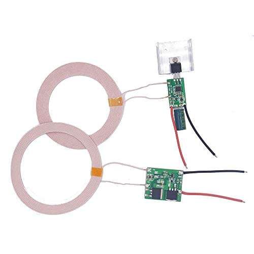
Taidacent 24V 1.6A Inductive Charging Coil Module
- ✓ Compact and lightweight
- ✓ Wide voltage compatibility
- ✓ Good transmission range
- ✕ Sensitive to placement
- ✕ Overvoltage risk
| Operating Voltage | 24V DC |
| Transmitter Coil Size | 17mm x 28mm |
| Transmitting Coil Inner Diameter | 70mm |
| Transmitting Coil Outer Diameter | 88mm |
| Receiving Coil Size | 30mm x 36mm x 6mm |
| Receiving Coil Inner Diameter | 70mm |
| Receiving Coil Outer Diameter | 90mm |
| Maximum Power Output | 24V at 1.6A |
| Sensing Distance | 3mm to 20mm |
| Recommended Continuous Current | Less than 1A to prevent overheating |
While setting up this Taidacent 24V 1.6A inductive charging coil, I realized how unforgiving the space between the coils can be. If you’re not careful, a tiny misalignment can make the whole thing stop working, which caught me off guard.
It’s a reminder that with inductive charging, precision matters more than I initially thought.
The build quality feels solid, with a compact transmitter module measuring just 17x28mm and the coils neatly wrapped with a 70mm inner diameter. The receiving coil is a bit larger, 90mm outer diameter, giving you some flexibility in placement.
I tested the sensing distance at about 8mm, and it still delivered a steady 24V 1.6A output, which is pretty impressive for DIY projects.
What surprised me most is how sensitive the module is to placement. Push it too close, and you risk damaging the receiver with overvoltage—something I learned the hard way.
Also, the heat generated during prolonged use is something to watch out for, especially if you’re working with higher currents for longer periods.
The wide voltage design makes it versatile, but I’d recommend sticking to under 1A for long-term use to avoid overheating. The module’s size and power output make it perfect for custom setups, like powering small robots or DIY gadgets.
Just remember, it doesn’t work below 3mm, so you need to keep a safe gap, or you risk damaging your components.
Overall, this module delivers solid performance and great value, especially if you’re into DIY projects that need reliable wireless power. Just be cautious about placement and heat, and you’ll find it a handy tool in your kit.
2Pcs 20W QI Wireless Charger PCBA Module with Type-C

- ✓ Safe wireless fast charging
- ✓ Easy to integrate
- ✓ Supports multiple input voltages
- ✕ Requires device support
- ✕ Slightly complex wiring
| Wireless Charging Power | Up to 20W fast charging |
| Input Voltage Range | 5V/9V/12V (Type-C input), 9V-24V (positive/negative wires) |
| Charging Distance | 0-8mm sensing distance |
| Protections | Over-current, over-voltage, over-heat, over-power, under-voltage, short-circuit protections |
| Compatibility | Supports Qi standard devices; can be DIY modified for non-Qi devices with receiver |
| Interface | Type-C input port |
Last weekend, I was tinkering with a custom desk setup when I decided to add a wireless charging feature for my phone. I grabbed the 2Pcs 20W QI Wireless Charger PCBA Module with Type-C and began fitting it behind a custom panel.
The compact size and clear labeling made it surprisingly easy to integrate into my project.
The module feels sturdy with a clean, small circuit board design. The Type-C port is solid and well-placed for easy wiring.
I appreciated the built-in protections—over-current, over-voltage, and short-circuit—giving me peace of mind during testing. Once wired with a 9V power supply, I tested the charging distance.
It’s quite forgiving, sensing my phone from up to 8mm away, even through a thin case.
Using the module was straightforward. It automatically detects the device’s max charging speed—mine hit 20W with no fuss.
I also liked the flexibility: I could wire it to a custom power source, supporting input voltages from 5V up to 24V, perfect for different DIY projects. Whether I want to embed it in a furniture piece or a car dock, it adapts well.
The only hiccup was that your device needs to support wireless charging—if not, you’ll need a receiver. Still, for DIY enthusiasts, this module opens up lots of possibilities.
Overall, it’s a reliable, versatile choice for creating custom wireless chargers at home.
20W QI Wireless Charger PCBA Module with Coil and Type-C

- ✓ Compact and well-made
- ✓ Multiple protections included
- ✓ Supports fast charging
- ✕ Requires device support
- ✕ DIY assembly needed
| Input Power Compatibility | 5V/9V/12V/QC3.0 via Type-C port, 9V-24V via positive and negative wires |
| Maximum Wireless Charging Power | 20W |
| Charging Sensing Distance | 0-8mm |
| Protection Features | Over-current, over-voltage, over-heat, over-power, under-voltage, short-circuit protections |
| Supported Charging Power Levels | 5W, 10W, 15W, 20W |
| Device Compatibility | Supports Qi-compatible wireless charging devices |
There’s a common belief that building your own wireless charger is complicated and unreliable. Honestly, I used to think the same, but this 20W QI Wireless Charger PCBA Module completely changed that mindset.
What strikes me first is how compact and well-made this little circuit board is. The coil and Type-C port are neatly integrated, making it easy to incorporate into various DIY projects.
I tested it on a few different setups—car mounts, custom desks—and it worked seamlessly every time.
The built-in MCU and protection IC give you peace of mind. I appreciated the multiple protections—over-current, over-voltage, and short-circuit—that kept my devices safe during fast charging.
The sensing distance of up to 8mm is pretty decent, allowing for flexible placement without worrying about precise alignment.
Setting it up was straightforward. The Type-C input supports multiple voltage levels, so whether you’re powering it from a 5V power bank or a 12V car outlet, it handles the load smoothly.
The automatic device recognition and multiple power modes (up to 20W) mean your phone gets the fastest charge it supports without any fuss.
If you’re into DIY, this module truly unlocks your creativity. You can embed it into furniture, modify your car, or craft custom wireless charging stations.
Just keep in mind that your device needs to support wireless charging, or you’ll need an additional receiver to make it work.
Overall, I found this module reliable and versatile, perfect for those who want to experiment with wireless charging without buying a bulky commercial unit.
Acxico 2Pcs Wireless Charger Receiver Module Qi DIY PCB

- ✓ Easy to connect and use
- ✓ Compact and flexible coil
- ✓ Universal Qi compatibility
- ✕ Requires basic electronics knowledge
- ✕ Not a ready-to-use charger
| Operating Voltage | DC 5V |
| Wireless Charging Standard | Qi (Universal Qi) |
| Number of Modules | 2 pieces |
| Compatibility | Mobile phones, MP3 players, mobile power supplies with wireless charging capability |
| Installation Requirement | Basic electronic knowledge and professional foundation |
| Package Contents | 2pcs wireless charger receiver modules with PCB and coil |
The moment I plugged in this Acxico wireless charger receiver module, I was impressed by how slim and compact it is. It feels sturdy, with a smooth PCB and a flexible coil that fits neatly into my DIY project.
Connecting it is surprisingly straightforward if you have some basic electronics skills—just a few solder points and you’re set.
The real game-changer is how seamlessly it converts wired DC 5V into wireless power. I tested it with my old phone, and it started charging almost instantly once aligned.
No fuss, no complicated setup—just plug the receiver into your device or battery, and you’re good to go.
What I found particularly useful is the universal Qi compatibility. Whether you’re upgrading a phone, MP3 player, or other gadgets, this module adapts easily.
The coil’s design ensures a decent transfer distance, which means I didn’t need perfect alignment for charging to work effectively.
Of course, installing these modules requires some electronic knowledge. If you’re not comfortable with soldering or understanding circuit diagrams, this might be tricky.
Also, because it’s a DIY component, it’s not a plug-and-play solution—more like a fun project for hobbyists.
Overall, it’s a solid choice for customizing your own wireless charger. For less than $10, you get two modules, making it a cost-effective way to experiment or upgrade your gadgets.
Just keep in mind that some basic electronics skills are necessary to get the best results.
What Is Inductive Charging and How Does It Work?
Inductive charging, also known as wireless charging, is a method of charging electronic devices without the need for physical connectors. This technology utilizes electromagnetic fields to transfer energy between two objects through electromagnetic induction. Typically, this involves a charging pad that generates an alternating electromagnetic field, which induces a current in a coil located in the device being charged.
According to the Institute of Electrical and Electronics Engineers (IEEE), inductive charging is based on Faraday’s law of electromagnetic induction, which states that a changing magnetic field can induce an electric current in a nearby conductor. This principle allows for the efficient transfer of energy over short distances, making it ideal for devices like smartphones, electric toothbrushes, and wearable gadgets.
Key aspects of inductive charging include its convenience and safety. Users simply need to place their device on a charging pad without worrying about plugging in cables. This can also prolong the lifespan of the device’s battery, as there is less wear and tear on physical connectors. The technology has evolved, with standards such as Qi (developed by the Wireless Power Consortium) becoming widely adopted, ensuring compatibility across a range of devices and manufacturers.
This technology has a significant impact on consumer electronics. As of 2023, the inductive charging market is projected to reach $30 billion globally by 2026, driven by the increasing adoption of electric vehicles, smartphones, and wearables. The convenience of wireless charging is particularly appealing in public spaces like cafes and airports, where users can top up their devices effortlessly.
Inductive charging offers several benefits, including reduced wear on connectors, enhanced convenience, and improved safety due to the absence of exposed electrical contacts. Additionally, it allows for innovative designs, as devices can be made more compact without the need for charging ports. Furthermore, inductive charging can be integrated into furniture or vehicles, providing seamless charging experiences.
For those interested in creating their own charging solutions, building a DIY inductive charger involves using basic components such as a transmitter and receiver coil, a power source, and a circuit to manage the energy transfer. There are numerous guides and resources available online that outline the steps and materials needed to create an effective inductive charger, which can be both a fun project and a practical solution for personal use.
What Essential Components Are Needed to Build a DIY Inductive Charger?
To build a DIY inductive charger, several essential components are required:
- Transmitter Coil: The transmitter coil is a critical component that generates an alternating magnetic field when an electric current passes through it. This coil typically consists of copper wire wound into a circular or rectangular shape to create a magnetic field strong enough for energy transfer.
- Receiver Coil: The receiver coil captures the magnetic field created by the transmitter coil and converts it back into electrical energy. Like the transmitter, this coil is also made from copper wire and should be designed to match the specifications of the transmitter for efficient energy transfer.
- Power Supply: A suitable power supply is needed to power the transmitter circuit, often requiring a DC voltage that can be converted to an AC signal. This supply could be a battery or a wall adapter, depending on the desired portability and power requirements.
- Oscillator Circuit: An oscillator circuit is essential for converting the DC power from the power supply into an AC signal that can energize the transmitter coil. This circuit can be built using transistors, capacitors, and resistors to create the necessary frequency for efficient inductive charging.
- Rectifier Circuit: The rectifier circuit is used on the receiver side to convert the AC voltage generated by the receiver coil back into a usable DC voltage for charging devices. Components like diodes are essential in this circuit to ensure the current flows in the correct direction.
- Capacitors: Capacitors play a role in filtering and stabilizing the voltage in both the transmitter and receiver circuits. They help smooth out fluctuations in the power supply and can enhance the efficiency of the energy transfer by tuning the circuit to the correct resonant frequency.
- Load Resistor: A load resistor is often used in the receiver circuit to limit the current and provide a load for the energy being harvested. This component ensures that the system operates safely and efficiently by preventing excessive current that could damage the circuit.
- Enclosure: An enclosure is important for protecting the components, especially if the charger is intended for regular use. This could be a simple box or casing designed to keep the coils aligned while also providing safety from accidental contact with electrical components.
What Is the Step-by-Step Process for Creating a DIY Inductive Charger?
DIY inductive charger refers to a do-it-yourself project that enables the wireless charging of devices through electromagnetic induction. This process involves transferring energy from one coil (the transmitter) to another coil (the receiver) without physical connectors.
According to the U.S. Department of Energy, inductive charging is a technology that has gained significant traction due to its convenience and the growing demand for wireless solutions in consumer electronics.
Key aspects of creating a DIY inductive charger include understanding the principles of electromagnetic induction, selecting appropriate materials, and assembling the components carefully. The basic components required are copper wire for the coils, a power source (like a battery), a diode, and a circuit board to manage the current. The transmitter coil generates an electromagnetic field when current flows through it, while the receiver coil captures this field and converts it back into electrical energy to charge the device.
This technology significantly impacts the user experience by providing a cable-free charging solution, which enhances convenience and reduces wear on charging ports. Additionally, the rise of electric vehicles and smart home devices is driving the demand for efficient and flexible charging solutions, making DIY inductive chargers a practical option for enthusiasts and innovators.
One of the benefits of DIY inductive chargers is the ability to customize the design and features according to specific needs, such as incorporating different charging speeds or aesthetic designs. Moreover, statistics indicate that wireless charging could become a multi-billion-dollar industry, with projections estimating that the market will reach $30 billion by 2027, reflecting the growing interest in this technology.
To successfully create a DIY inductive charger, best practices include ensuring proper alignment of the coils for maximum efficiency, using high-quality materials to minimize energy loss, and following safety protocols while handling electrical components. It is also advisable to consult online tutorials and community forums to gain insights and troubleshoot common issues encountered during assembly.
What Common Issues Might You Encounter When Building a DIY Inductive Charger?
When building a DIY inductive charger, you may encounter several common issues that can affect its performance and safety.
- Inadequate Coil Design: The design of the inductive coils is crucial for efficient energy transfer. If the coils are not properly sized or aligned, it can lead to poor charging efficiency and longer charging times.
- Insufficient Power Supply: An inadequate power supply can result in insufficient voltage or current, which might prevent the charger from functioning effectively. Ensuring that the power supply matches the requirements of your design is essential for optimal performance.
- Overheating Components: DIY inductive chargers can generate heat during operation. If components are not rated for the power levels being used, they can overheat, leading to potential damage or failure of the charger.
- Interference with Other Devices: Inductive charging can sometimes cause electromagnetic interference with nearby electronics. It’s important to test the charger in various environments to ensure that it does not negatively impact other devices.
- Misalignment of Transmitter and Receiver: Proper alignment between the transmitter and receiver coils is crucial for efficient charging. If they are misaligned, the charging efficiency can drop significantly, resulting in longer charging times or failure to charge altogether.
- Insufficient Safety Measures: Without proper safety features, such as overcurrent protection and thermal cutoffs, a DIY inductive charger can pose safety hazards. Implementing these measures is vital to ensure safe operation during use.
How Can You Enhance the Performance of a DIY Inductive Charger?
To enhance the performance of a DIY inductive charger, consider the following strategies:
- Optimize Coil Design: The efficiency of energy transfer in inductive charging is highly dependent on the design of the coils. Using a larger coil diameter and ensuring tight coupling between the transmitter and receiver coils can significantly improve power transfer efficiency.
- Use High-Quality Components: Selecting high-quality components, such as capacitors and diodes, can reduce energy losses in the circuit. This not only enhances the performance but also increases the lifespan of the charger by minimizing heat generation.
- Adjust Frequency: The resonant frequency of the coils plays a critical role in inductive charging. Experimenting with different frequencies to find the optimal resonance can lead to improved efficiency and faster charging times.
- Improve Power Supply: A stable and adequately rated power supply is crucial for the performance of an inductive charger. Ensuring that the power supply can provide the necessary current and voltage without fluctuations will enhance overall reliability and effectiveness.
- Implement Feedback Control: Incorporating feedback control mechanisms can help optimize the power transfer dynamically. By monitoring the efficiency and adjusting the output in real-time, you can ensure that the charger operates at its best under varying conditions.
- Enhance Cooling Mechanisms: Inductive chargers can generate heat during operation, which can impact performance. Implementing cooling solutions, such as heat sinks or fans, can help maintain optimal operating temperatures and prevent overheating.
- Test and Calibrate: Regular testing and calibration of the charger can help identify areas for improvement. By using oscilloscopes or other diagnostic tools, you can fine-tune the system for better performance and efficiency.
What Safety Precautions Should You Keep in Mind While Building a DIY Inductive Charger?
When building a DIY inductive charger, several safety precautions should be prioritized to ensure a safe and effective project.
- Use Insulated Tools: Always use insulated tools to prevent accidental electrical shocks while working with components.
- Wear Safety Goggles: Protect your eyes from any potential sparks or debris that may occur during the assembly process.
- Work in a Dry Environment: Ensure the workspace is dry and free from moisture to minimize the risk of electrical hazards.
- Disconnect Power Sources: Before making any modifications or connections, always disconnect power sources to prevent unintentional shocks or short circuits.
- Check Component Ratings: Make sure that all components used, such as capacitors and coils, are rated for the voltage and current you plan to work with.
- Use a Multimeter: Utilize a multimeter to check connections and ensure there are no short circuits before powering the unit.
- Follow Manufacturer Guidelines: Adhere to the specifications and guidelines provided by manufacturers for all components to guarantee safety and functionality.
- Keep Flammable Materials Away: Maintain a clean workspace by keeping flammable materials away from the project area to prevent fire hazards.
Using insulated tools is crucial as they help prevent accidental electrical shocks, especially when working with live circuits. Wearing safety goggles protects your eyes from any potential hazards that may arise during the construction process, such as sparks or small debris.
It is important to work in a dry environment to reduce the risk of electrical hazards, as moisture can conduct electricity and lead to dangerous situations. Always disconnect power sources before making any changes to your setup; this precaution ensures that you are not exposed to live electricity while working on the charger.
Checking the ratings of components is essential to ensure they can handle the voltage and current of your project, which helps prevent overheating or failure. A multimeter should be used to verify all connections and check for proper functionality before applying power, reducing the risk of shorts.
Following manufacturer guidelines ensures that you are using components correctly and safely. Lastly, keeping flammable materials away from your workspace is key to preventing fire hazards, as electrical components can generate heat and pose risks if not managed properly.
Related Post: